Sustainability

Industrial water reuse and recycling system

Industrial Water Reuse: The Complete Guide for 2026

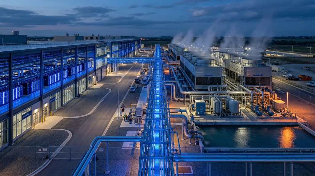
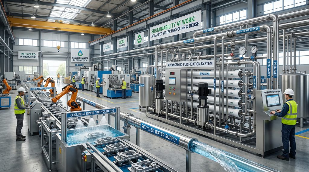
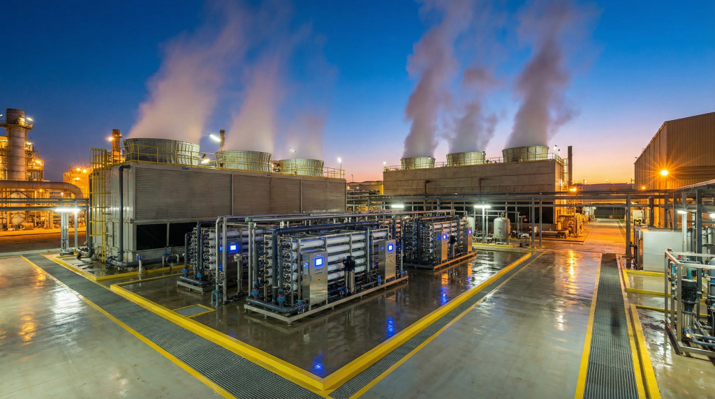
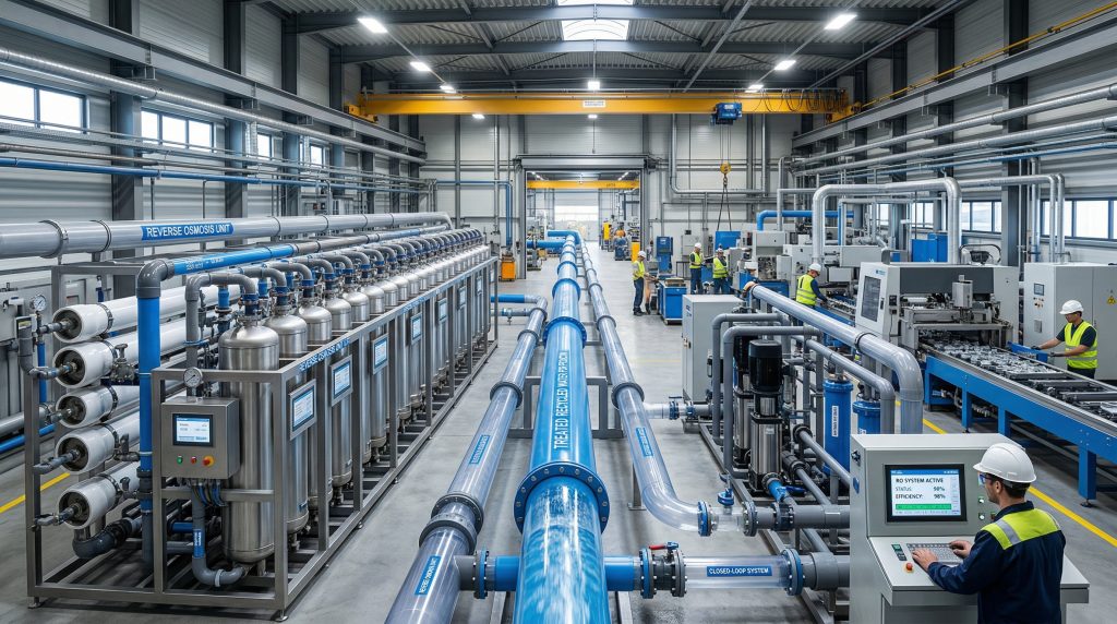
Why Is Industrial Water Reuse Surging in 2026? Water scarcity is no longer a future risk—it is an operating reality. According to the World Resources Institute, 25 countries housing one-quarter of the global population face “extremely high” baseline water stress every year. For manufacturers, this translates directly into supply uncertainty, rising utility rates, and increasingly stringent discharge permits. The numbers tell the story. The global industrial water reuse and recycling market, valued at approximately $14.2 billion in 2022, is on track to reach $23.4 billion by 2028, according to MarketsandMarkets research. That growth is not speculative. It is being driven by three converging forces: tightening environmental regulations, escalating freshwater costs, and the rapid mainstreaming of ESG (Environmental, Social, and Governance) reporting requirements. In the Western United States, the urgency is particularly acute. The Colorado River Basin continues to face historic shortfalls. The Great Salt Lake has lost roughly two-thirds of its water volume since the 1980s, threatening both ecosystems and the regional economy. For industrial operators in Utah and neighboring states, reducing freshwater intake through reuse is becoming less of a sustainability aspiration and more of a license-to-operate requirement. What Are the Main Types of Industrial Water Reuse? Not all reuse is the same. The treatment required, the economics involved, and the regulatory considerations vary significantly depending on which water stream you are targeting. Understanding these distinctions is the first step toward building a system that actually delivers a return. Process Water Recycling Process water—used directly in manufacturing operations like rinsing, washing, and product formulation—represents the largest volume of industrial water consumption in most facilities. In food and beverage manufacturing alone, process water can account for 60–80% of total facility water use. Recycling process water typically requires multi-stage treatment to meet the quality specifications of the original application. A pharmaceutical rinse water, for example, demands different purity than a metal finishing rinse. The treatment train is designed around the specific contaminants present and the quality targets required. Common treatment sequences for process water reuse include: Screening and sedimentation to remove suspended solids Biological treatment (for high-BOD streams) to reduce organic loading Ultrafiltration (UF) to remove particles, bacteria, and colloids down to 0.01 microns Reverse osmosis (RO) to remove dissolved salts, organics, and trace contaminants UV disinfection or ozone for final microbial control Recovery rates of 85–95% are achievable with properly designed UF-RO systems, meaning that for every 100 gallons of wastewater entering the system, 85–95 gallons are returned as reusable process water. Cooling Tower Blowdown Recovery Cooling towers are water-intensive. The Electric Power Research Institute (EPRI) estimates that cooling systems account for approximately 40% of industrial water withdrawals in the United States. As water circulates through a cooling tower, evaporation concentrates dissolved minerals. To prevent scaling and corrosion, a portion of this concentrated water—called blowdown—must be discharged and replaced with fresh makeup water. Treating and recycling blowdown water with RO allows facilities to increase their cycles of concentration, dramatically reducing both freshwater makeup requirements and discharge volumes. A facility operating at 3 cycles of concentration that moves to 6 cycles through blowdown recovery can cut its makeup water demand by roughly 30–40%. The treatment approach is relatively straightforward: chemical softening or antiscalant dosing, followed by RO. The concentrated RO reject can either be sent to a zero liquid discharge (ZLD) system or managed through evaporation ponds, depending on local discharge regulations. Boiler Feed Water Recovery Boiler systems require high-purity water to prevent scaling, corrosion, and carryover. Traditionally, facilities use freshwater treated through softening and deionization. Recovering and treating condensate return and other suitable wastewater streams for boiler feed reduces both water and energy costs, since recovered condensate is already at elevated temperatures. Treatment for boiler feed reuse typically involves UF followed by two-pass RO or RO plus electrodeionization (EDI) to achieve the low TDS and silica levels required. The energy savings from using warm recovered water instead of cold municipal supply can be substantial—often 5–15% of total boiler fuel costs. Which Technologies Drive Modern Water Reuse Systems? The technology landscape for industrial water reuse has matured considerably over the past decade. Today’s systems combine multiple treatment technologies in engineered sequences that are far more reliable and cost-effective than the early-generation reuse plants. Here is a practical overview of the core technologies. Ultrafiltration (UF) UF membranes operate with pore sizes between 0.01 and 0.1 microns, effectively removing suspended solids, bacteria, viruses, and colloidal material. UF serves as the workhorse pretreatment step before RO in nearly all modern reuse systems. By protecting the RO membranes from fouling, UF extends membrane life by 20–40% and reduces cleaning frequency. Modern UF systems use either hollow-fiber or flat-sheet membrane configurations, with hollow fiber being the dominant choice for industrial applications due to higher packing density and easier backwash procedures. Reverse Osmosis (RO) RO remains the gold standard for removing dissolved contaminants from water. Operating at pressures between 100 and 600 psi depending on feedwater salinity, RO membranes reject 95–99.5% of dissolved salts, organic compounds, and most microcontaminants including PFAS, pharmaceuticals, and heavy metals. For industrial reuse applications, AMPAC commercial and industrial RO systems are engineered with the specific feedwater chemistry and target water quality in mind. Single-pass RO achieves permeate TDS suitable for most cooling and general process applications. Two-pass configurations or RO-EDI combinations deliver the higher purity required for boiler feed and semiconductor manufacturing. Nanofiltration (NF) NF membranes sit between UF and RO in terms of rejection capability. They remove divalent ions (calcium, magnesium, sulfate) while allowing a portion of monovalent ions (sodium, chloride) to pass through. This selectivity makes NF ideal for applications where complete demineralization is unnecessary but hardness and specific contaminants must be removed. NF operates at lower pressures than RO—typically 70–150 psi—which translates to 20–40% lower energy consumption. For cooling tower makeup or certain process applications, NF can be the more economical choice. UV Disinfection and Advanced Oxidation For reuse applications requiring microbial control, UV disinfection at 254 nm wavelength provides effective inactivation of bacteria, viruses, and protozoa without

Industrial Water Reuse: The Complete Guide for 2026 Read More »

Data center cooling systems water consumption

AI Data Centers Are Draining Water: The Hidden Crisis of 2026

How Much Water Do AI Data Centers Actually Consume? The artificial intelligence boom has created a water consumption problem that most people do not know exists. Every time a large language model generates a response, processes an image, or trains on a new dataset, it consumes electricity—and that electricity generates heat. Removing that heat requires cooling, and the most common industrial cooling method is evaporative cooling, which consumes water. The numbers are staggering. A 2024 study by researchers at the University of California, Riverside estimated that training a single large AI model like GPT-4 consumed approximately 700,000 liters (185,000 gallons) of water for cooling. For inference (running the trained model to answer queries), the same researchers estimated that generating 10-50 responses consumes roughly 500 milliliters (about one bottle) of water. Scale that to billions of daily queries across all major AI platforms, and the aggregate consumption is measured in hundreds of millions of gallons per day. The International Energy Agency (IEA) projects that global data center electricity consumption will more than double between 2022 and 2026, reaching 1,000 TWh annually—roughly equivalent to Japan’s total electricity consumption. Because the majority of this electricity ultimately becomes waste heat that must be rejected, cooling water demand scales proportionally. Industry analysts project global data center water consumption will reach 280 billion liters (74 billion gallons) annually by 2028. Why Do Data Centers Need So Much Water for Cooling? Data center cooling systems must reject enormous amounts of waste heat to keep server hardware operating within safe temperature ranges. The thermal density of modern AI hardware drives this requirement to levels unprecedented in commercial computing. Traditional vs. AI Server Heat Generation A traditional data center rack hosting conventional servers dissipates 5-15 kW of heat. An AI training rack equipped with the latest GPU accelerators (NVIDIA H100/H200, AMD MI300X) can dissipate 40-120 kW per rack—and next-generation liquid-cooled AI racks are pushing toward 200 kW. This 3-10x increase in heat density means that cooling systems designed for traditional computing are fundamentally inadequate for AI workloads. How Evaporative Cooling Works The dominant cooling architecture for large data centers uses evaporative cooling towers. Warm water from the data center’s cooling loop is circulated through the cooling tower, where a portion of it evaporates into the atmosphere. The evaporation process absorbs heat (latent heat of vaporization), cooling the remaining water, which is then recirculated back through the data center. This is extremely energy-efficient—evaporative cooling can achieve Power Usage Effectiveness (PUE) ratios of 1.1-1.3, meaning only 10-30% of total energy goes to cooling infrastructure. The trade-off is water. For every 1 MW of heat rejected through evaporative cooling, approximately 1,500-2,500 gallons per hour of water is consumed through evaporation, drift, and blowdown. A 100 MW hyperscale data center—a common size for AI-focused facilities—can consume 3-6 million gallons of water per day during peak summer operation. Blowdown: The Overlooked Water Stream Evaporation concentrates dissolved minerals in the remaining cooling water. Left unchecked, these minerals would scale heat exchange surfaces and corrode piping. To prevent this, cooling towers continuously discharge a portion of the concentrated water (blowdown) and replace it with fresh makeup water. Blowdown typically represents 20-40% of total cooling tower water consumption, depending on the cycles of concentration at which the system operates. Blowdown is the water stream where treatment technology can have the greatest impact. Rather than discharging concentrated blowdown to the sewer and replacing it with fresh municipal water, data centers can recover 70-80% of blowdown water using reverse osmosis, recycling it as makeup water and dramatically reducing total water consumption. Why Is Utah Becoming a Data Center Hub—and What Are the Water Risks? Utah has become one of the fastest-growing data center markets in the Western United States. Several factors make the state attractive for hyperscale and enterprise data center development: Low electricity costs: Utah’s blended commercial electricity rate averages $0.08-$0.10/kWh, well below the national average and significantly below rates in California, Oregon, and Washington where data center markets are saturated. Cool climate: Utah’s semi-arid climate with low humidity enables extensive use of free cooling (using ambient air for heat rejection) during cooler months, reducing the hours per year that evaporative cooling is required. Fiber connectivity: Salt Lake City is a major fiber optic junction point for transcontinental routes, providing low-latency connectivity to both coasts. Business environment: Utah’s tax structure, permitting processes, and workforce availability are favorable for large-scale data center construction. Seismic stability: Compared to some other Western states, Utah’s geological risk profile (while not zero) is manageable with proper engineering. The water risk, however, is significant. Utah is the second-driest state in the nation by average annual precipitation. The Wasatch Front, where the majority of data center development is occurring, is already under persistent drought conditions. Municipal water supplies are strained, and large-scale industrial water users face increasing scrutiny from regulators, water conservancy districts, and the public. A single 50 MW data center consuming 2-3 million gallons per day represents a meaningful draw on local water resources—equivalent to adding a small city’s water demand to an already stressed system. Multiple large facilities in the same water district compound the impact. For data center operators, this creates both a reputational risk and an operational risk: communities may resist new projects, and water districts may impose allocation limits or surcharges that affect operating economics. How Can Data Centers Reduce Water Consumption? Data center operators have multiple strategies available to reduce water consumption, ranging from cooling system optimization to on-site water treatment and recycling. The most effective approach combines several strategies. Strategy 1: Optimize Cooling Tower Cycles of Concentration Cycles of concentration (COC) is the ratio of dissolved solids in blowdown water to dissolved solids in makeup water. Higher COC means less blowdown and less makeup water. Most cooling towers operate at 3-5 COC. By improving makeup water quality with RO pre-treatment, data centers can increase COC to 8-15 cycles, reducing total water consumption by 20-40% compared to untreated municipal water. Cycles of Concentration Blowdown as % of

AI Data Centers Are Draining Water: The Hidden Crisis of 2026 Read More »

Water recycling system in manufacturing plant

Water Reuse in Manufacturing: How Industrial Plants Are Cutting Costs with RO Recycling

Water Is a Production Input, Not a Disposable Resource For most of the 20th century, manufacturing plants treated water the same way they treated packaging material—use it once and throw it away. Freshwater came in from the municipal supply or a well, passed through the process, and went out to the sewer or a discharge permit. The cost was negligible, the supply was reliable, and nobody thought twice about it. That model is breaking down. Municipal water rates in major industrial regions have increased 40-60% over the past decade. Discharge permits are getting stricter and more expensive. Drought conditions and competing agricultural demand are making water allocation less predictable. And in some regions—the American Southwest, parts of the Middle East, Northern China, and Southeast Australia—industrial water availability is genuinely constrained. The result is a fundamental shift in how manufacturers think about water. Reverse osmosis-based recycling systems are at the center of that shift, enabling plants to recover and reuse 75-90% of their process wastewater. The economics have reached a tipping point where water recycling isn’t just an environmental nice-to-have—it’s a competitive advantage that directly impacts the bottom line. The Business Case: Real Numbers on Water Recycling ROI Let’s start with the math, because that’s what drives capital approval in manufacturing. The Rising Cost of Water A mid-sized manufacturing plant in Southern California consuming 200,000 gallons per day currently pays roughly: Water supply: $6-$10 per 1,000 gallons (including tiered pricing and surcharges) Sewer discharge: $8-$14 per 1,000 gallons (depending on strength of discharge) Combined water cost: $14-$24 per 1,000 gallons Annual water expense: $1,000,000-$1,750,000 Now consider an RO recycling system that recovers 80% of that wastewater for reuse: Reduced freshwater purchase: 160,000 GPD saved = $350,000-$584,000/year Reduced sewer discharge: 160,000 GPD diverted = $467,000-$817,000/year Total annual savings: $817,000-$1,400,000 RO recycling system OPEX (energy, chemicals, membranes, labor): $150,000-$300,000/year Net annual savings: $517,000-$1,100,000 With system capital costs ranging from $400,000 to $1,200,000 for a 200,000 GPD installation (depending on wastewater complexity and required permeate quality), the payback period typically falls between 8 months and 2.5 years. That’s a capital investment decision that sells itself. How Closed-Loop Water Systems Work in Manufacturing A closed-loop (or near-closed-loop) water recycling system captures process wastewater, treats it to the required quality, and returns it to the process. The basic flow path looks like this: Collection and equalization: Wastewater from various process streams is collected in an equalization tank that buffers flow and concentration fluctuations. Primary treatment: Removal of suspended solids, oils, and gross contaminants through screening, dissolved air flotation (DAF), or oil-water separation. Pre-treatment for RO: Multimedia filtration, activated carbon (for chlorine and organics), and cartridge filtration to protect the membranes. For high-fouling wastewater, ultrafiltration (UF) as a pre-treatment step significantly improves RO performance. Reverse osmosis: The core treatment step. The RO system removes 95-99%+ of dissolved salts, organics, and contaminants, producing permeate that meets or exceeds process water quality requirements. Post-treatment: pH adjustment, remineralization, or UV disinfection as needed for the specific reuse application. Concentrate management: The 10-25% reject stream (concentrate) still needs disposal—typically to the sewer, an evaporator, or in some cases, further concentration through a high-recovery RO or zero-liquid-discharge (ZLD) system. Industry Case Studies: Water Recycling in Action Automotive Manufacturing Automotive plants are water-intensive. A typical vehicle assembly plant with painting, metal finishing, and cooling operations consumes 500,000-1,000,000 gallons per day. Paint shop rinse water, in particular, contains metals, phosphates, and surfactants that require treatment before discharge. A Midwest assembly plant installed a 300,000 GPD industrial RO system to treat combined rinse water from their electrocoat and phosphate pretreatment lines. The system achieves 80% recovery, producing permeate with less than 50 ppm TDS—cleaner than their incoming municipal supply. Annual water and sewer savings exceeded $900,000, with additional savings from reduced chemical consumption in their paint pretreatment (since the recycled water has lower mineral content than the original supply). The system paid for itself in 14 months. Food and Beverage Processing Food plants face unique challenges: high organic loading (BOD/COD), seasonal production variability, and strict hygiene requirements for process water. Dairy processing, in particular, generates large volumes of whey-laden wastewater with high protein and lactose content. A cheese manufacturer in Wisconsin installed a UF + RO system to treat CIP (clean-in-place) rinse water and separator wastewater. The UF stage removes fats and proteins; the RO stage removes dissolved minerals and remaining organics. Recovery rate: 85%. The recycled water is used for non-product-contact applications (floor washing, boiler makeup, cooling tower makeup), offsetting 170,000 GPD of freshwater purchase. The bonus: the UF concentrate is rich in whey protein and is sold as animal feed supplement, creating a secondary revenue stream. Textile and Dyeing Textile dyeing operations consume enormous amounts of water—typically 25-100 gallons per pound of fabric processed. The wastewater is highly colored, contains residual dyes, salts (often 2,000-5,000 ppm TDS from sodium sulfate or sodium chloride used in the dye process), surfactants, and sizing chemicals. A denim finishing plant in North Carolina installed a multi-stage treatment system: biological treatment (to remove BOD), ozonation (for color removal), UF, and then RO. The RO system recovers 75% of the treated wastewater for reuse in the dye process. Since the recycled water has very low TDS, it actually improves dye uptake efficiency, reducing dye chemical consumption by 8-12%. Annual combined savings in water, sewer, and chemicals: approximately $650,000. Pre-Treatment: The Make-or-Break Factor Industrial wastewater is far more challenging to treat with RO than municipal water or groundwater. The single biggest reason industrial water recycling projects fail isn’t the RO system—it’s inadequate pre-treatment. Common Pre-Treatment Failures Oil and grease carryover: Even trace amounts of oil (>0.1 ppm) will foul RO membranes. If your wastewater contains any oil, you need oil-water separation followed by organoclay or activated carbon polishing upstream of the RO. Silica concentration: As RO concentrates the reject stream, silica can reach supersaturation and precipitate on the membrane. If feedwater silica exceeds 20-30 ppm, you need to limit recovery rate or add silica-specific antiscalant. Biological growth: Warm, nutrient-rich

Water Reuse in Manufacturing: How Industrial Plants Are Cutting Costs with RO Recycling Read More »

Solar-powered desalination system in remote location

Solar-Powered Desalination: Off-Grid Water Purification for Remote Locations

When the Grid Ends, the Water Problem Begins There are roughly 2.2 billion people worldwide without access to safely managed drinking water. A significant portion of them live in coastal or island communities where seawater is abundant but fresh water is scarce—and where electrical grid infrastructure simply does not exist. For decades, this created an impossible equation: desalination requires energy, energy requires infrastructure, and infrastructure requires capital that remote communities don’t have. Solar-powered reverse osmosis (Solar-RO) has fundamentally changed that equation. By coupling photovoltaic panels directly with RO desalination units, it’s now possible to produce thousands of gallons of potable water per day in locations with zero grid connectivity. The technology has matured past the pilot-project stage. Real systems are running in the Caribbean, sub-Saharan Africa, Southeast Asia, and disaster zones around the world—producing water at costs that are increasingly competitive with conventional diesel-powered alternatives. This article breaks down the engineering realities of solar-powered desalination: how the systems work, what they cost, how to size them, and where they make the most sense. How Solar-RO Systems Actually Work At its core, a solar-powered desalination system pairs two mature technologies: photovoltaic (PV) panels and reverse osmosis membranes. The PV array generates DC electricity, which either powers the RO high-pressure pump directly through a variable frequency drive (VFD) or charges a battery bank that provides consistent power regardless of solar conditions. Direct-Drive vs. Battery-Buffered Systems There are two primary architectures, and the choice between them has significant implications for cost and output: Direct-drive systems connect the PV array to the RO unit without battery storage. The system ramps up and down with solar irradiance—producing more water at midday and shutting down at night. These systems are simpler, cheaper (no battery cost), and have fewer components to maintain. The tradeoff is variable output. A well-designed direct-drive system in a location with 5-6 peak sun hours can produce water for roughly 8-10 hours per day. Battery-buffered systems include lithium-ion or lead-acid battery banks that store excess solar energy for use during cloudy periods or nighttime operation. This provides consistent 24-hour output but adds 25-40% to the capital cost. Battery replacement cycles (every 5-8 years for lithium, 3-5 for lead-acid) also increase long-term OPEX. For most off-grid applications, direct-drive systems with adequately sized water storage tanks offer the best balance of cost and reliability. You store water, not electricity—and water tanks are cheaper and more durable than batteries. PV Panel Sizing: Getting the Math Right Undersizing the solar array is the single most common mistake in solar-RO project design. Here’s how to approach the calculation properly. Energy Requirements by Water Type The energy needed depends heavily on feedwater salinity: Brackish water (1,000-10,000 ppm TDS): 1.0-3.0 kWh per cubic meter of permeate Seawater (30,000-45,000 ppm TDS): 3.5-6.0 kWh per cubic meter of permeate High-salinity seawater (Arabian Gulf, 45,000+ ppm): 5.5-8.0 kWh per cubic meter These figures include the high-pressure pump, controls, and pre-treatment. For a seawater system producing 10,000 gallons per day (37.8 m³/day), you’re looking at roughly 130-225 kWh of daily energy demand. Panel Array Calculation With modern monocrystalline panels rated at 400-550W each and assuming 5 peak sun hours per day (a reasonable average for tropical and subtropical locations): A 10,000 GPD seawater system needs approximately 30-50 kW of installed PV capacity That translates to 60-100 panels at 500W each Required roof or ground area: approximately 1,500-2,500 square feet Always add a 20-25% margin to account for panel degradation, soiling, temperature derating, and inverter losses. In dusty environments, budget for regular panel cleaning or consider automated cleaning systems. Energy Recovery Devices: The Efficiency Multiplier Modern seawater RO systems reject 55-65% of the feedwater as concentrated brine. That brine stream exits the membrane at high pressure—typically 800-1,000 psi for seawater applications. Energy recovery devices (ERDs) capture that hydraulic energy and transfer it back to the incoming feed stream. Isobaric ERDs like the PX Pressure Exchanger can recover up to 98% of the hydraulic energy in the brine stream, reducing the overall specific energy consumption of a seawater RO system from 6+ kWh/m³ down to 2.5-3.5 kWh/m³. That means you need 40-50% fewer solar panels for the same output—a massive cost reduction. For any solar-RO system larger than about 5,000 GPD treating seawater, an ERD is not optional. The payback period on the ERD alone is typically under 18 months when measured against the reduced PV array cost. Real-World Cost Data Let’s talk numbers. These are representative installed costs for turnkey solar-RO systems as of 2025-2026: Capital Costs (CAPEX) System Size Feedwater Installed Cost (USD) Cost per GPD 1,000 GPD Seawater $45,000-$75,000 $45-$75 5,000 GPD Seawater $120,000-$200,000 $24-$40 10,000 GPD Seawater $200,000-$350,000 $20-$35 5,000 GPD Brackish $50,000-$90,000 $10-$18 These costs include the RO unit, PV panels, mounting structures, inverters/VFDs, pre-treatment, water storage, and basic installation. Battery storage (if included) adds $15,000-$60,000 depending on capacity. Operating Costs (OPEX) This is where solar-RO really shines compared to diesel-powered alternatives. With no fuel costs, annual OPEX for a 10,000 GPD solar-seawater system runs approximately: Membrane replacement: $3,000-$6,000/year (assuming 3-5 year membrane life) Pre-treatment chemicals and cartridge filters: $1,500-$3,000/year Routine maintenance labor: $2,000-$5,000/year Panel cleaning and minor repairs: $500-$1,500/year Total annual OPEX: $7,000-$15,500 Compare that to a diesel-powered system of the same capacity, where fuel alone can run $25,000-$50,000 per year depending on local diesel prices. The levelized cost of water from solar-RO typically falls between $3-$8 per cubic meter for seawater applications—and below $2/m³ for brackish water. Applications: Where Solar-RO Makes the Most Sense Off-Grid Coastal Communities Island nations and remote coastal villages are the primary market. Systems ranging from 1,000 to 50,000 GPD serve communities of a few hundred to several thousand people. AMPAC’s seawater desalination systems are designed for exactly these conditions—compact, containerizable, and built for harsh marine environments where corrosion resistance and reliability are non-negotiable. Disaster Relief and Emergency Response After hurricanes, earthquakes, or tsunamis, municipal water infrastructure is often the first casualty. Solar-RO systems can be pre-staged in shipping containers and deployed within hours.

Solar-Powered Desalination: Off-Grid Water Purification for Remote Locations Read More »

Zero liquid discharge industrial wastewater treatment

Zero Liquid Discharge: The Future of Industrial Wastewater Management

Zero Liquid Discharge Was Once Considered Prohibitively Expensive. Tightening Regulations and Rising Water Costs Are Changing That Calculation Fast. The concept sounds absolute: zero liquid discharge. No wastewater leaves the facility. Every drop of water is either reused in the process or recovered as clean distillate, and the only byproduct is a dry solid—typically a cake or crystallized salt that can be landfilled or, in some cases, sold as a commodity chemical. Ten years ago, ZLD was a niche technology reserved for situations where discharge was physically impossible or regulators left no alternative. The economics were brutal—treatment costs of $10-$25 per thousand gallons versus $2-$5 for conventional treat-and-discharge. But the landscape has shifted. Inland facilities in water-stressed regions are running out of discharge options. The EPA’s 2024 Effluent Limitations Guidelines for steam electric power plants mandate zero discharge of flue gas desulfurization wastewater. States like California, Texas, and Colorado are imposing tighter discharge permits that push industries toward ZLD whether they planned for it or not. Meanwhile, the technology has gotten more efficient. Modern ZLD systems built around high-recovery reverse osmosis, mechanical vapor compression, and brine crystallization can achieve total water recovery at costs that, while still premium, are increasingly competitive with the alternative: losing your discharge permit and shutting down production. This article covers how ZLD systems work, where RO fits into the treatment train, which industries are adopting ZLD, and what the economics actually look like in 2025. What Zero Liquid Discharge Actually Means ZLD is exactly what it sounds like: an industrial facility that generates wastewater treats it to the point where no liquid effluent is discharged to surface water, groundwater, or the municipal sewer system. The treatment process separates wastewater into two streams: Clean water (distillate or permeate) that’s recycled back into the industrial process Solid residuals (salts, metals, or mineral concentrates) that are disposed of as solid waste or recovered for reuse ZLD is distinct from “minimal liquid discharge” (MLD), which reduces discharge volume by 90-95% but still produces a small concentrate stream that requires disposal. MLD is often a more cost-effective intermediate step for facilities that can’t justify full ZLD economics but need to dramatically reduce discharge volumes. The ZLD Treatment Train: Where RO Does the Heavy Lifting A modern ZLD system is not a single piece of equipment—it’s a carefully sequenced treatment train where each technology handles a specific concentration range. Here’s how the stages typically break down: Stage 1: Pretreatment Raw wastewater first undergoes chemical softening (lime/soda ash) to remove calcium, magnesium, silica, and metals that would foul downstream membranes and evaporators. Clarification and filtration follow. This step is critical—skipping or under-designing pretreatment is the fastest way to turn a ZLD project into a maintenance nightmare. Stage 2: Primary Reverse Osmosis (70-85% Recovery) The workhorse of water recovery. Standard industrial RO treats the pretreated wastewater at 70-85% recovery, producing clean permeate for reuse and a concentrate stream at 3-5x the feed water TDS. For a feed water at 5,000 ppm TDS, primary RO produces permeate at under 100 ppm TDS and concentrate at 15,000-25,000 ppm. AMPAC industrial RO systems are designed for this duty, with high-recovery configurations, chemical-resistant wetted materials, and PLC controls that handle the variable feed water quality typical of industrial wastewater applications. Stage 3: High-Recovery RO or Brine Concentrator (85-95% Total Recovery) The primary RO concentrate still contains recoverable water. High-recovery RO systems using specialized membranes (disc-tube or vibrating membrane systems like VSEP) can push recovery to 90-95% by managing the scaling and fouling that conventional RO cannot handle at high TDS levels. These systems operate at elevated pressures (600-1,200 psi) with specialized antiscalant programs. Alternatively, mechanical vapor compression (MVC) evaporators can concentrate the RO reject to 200,000-250,000 ppm TDS. MVC evaporators use a compressor to recycle the latent heat of evaporation, achieving thermal efficiency of 90%+ and energy consumption of 20-30 kWh per thousand gallons of distillate produced. Stage 4: Crystallizer or Evaporation Pond The final concentration step takes the brine from 200,000+ ppm to a dry solid. Forced-circulation crystallizers are the standard technology—they heat the brine to boiling in a recirculation loop, producing steam (recovered as clean distillate) and a slurry of crystallized salts that are dewatered in a filter press or centrifuge. Crystallizers are the most energy-intensive component of a ZLD system, consuming 50-80 kWh per thousand gallons of feed. This is precisely why maximizing RO recovery in Stages 2 and 3 is so important—every gallon that RO recovers is a gallon that doesn’t need to be evaporated at 3-5x the energy cost. The Economics: What ZLD Actually Costs Let’s put real numbers on this. For a 500,000 GPD industrial ZLD system treating wastewater with 5,000 ppm TDS: Component Capital Cost Operating Cost ($/1000 gal) Pretreatment (softening, clarification) $500K – $1M $1.50 – $2.50 Primary RO (80% recovery) $400K – $800K $1.00 – $2.00 High-recovery RO / Brine concentrator $1M – $3M $3.00 – $6.00 Crystallizer $2M – $5M $8.00 – $15.00 Total ZLD System $4M – $10M $13.50 – $25.50 Those operating costs look steep until you consider the alternatives. Deep well injection (where geologically feasible) costs $5-$15 per thousand gallons and requires permits that take 2-5 years to obtain. Trucking wastewater to an offsite disposal facility runs $0.05-$0.15 per gallon ($50-$150 per thousand gallons). And the cost of non-compliance—fines, production shutdowns, legal liability—dwarfs all of these numbers. The MLD Option: 90% of the Benefit at 50% of the Cost For facilities where regulations allow a small-volume discharge, minimal liquid discharge (MLD) eliminates the crystallizer—the most expensive component. An MLD system using pretreatment, primary RO, and high-recovery RO achieves 90-95% water recovery at $5-$10 per thousand gallons. The remaining 5-10% concentrate can often be disposed of through deep well injection, evaporation ponds, or permitted discharge at dramatically reduced volumes. Industries Driving ZLD Adoption Power Generation The EPA’s 2024 steam electric ELG revisions require zero discharge of flue gas desulfurization (FGD) wastewater, coal ash transport water, and flue gas mercury control wastewater. This affects coal

Zero Liquid Discharge: The Future of Industrial Wastewater Management Read More »

We Accept: VISA MasterCard AMEX Discover PayPal Authorize.net

© 2026 AMPAC Water Systems. All rights reserved. Manufactured in North America.

✓ 30+ Years Experience ✓ NSF Certified ✓ 500+ Installations Worldwide
Shopping Cart
A division of AMPAC USA - Commercial & Industrial Water Treatment Systems
Get a Free Quote
☎ Call (909) 548-4900
Ampac  Water Systems
Privacy Overview

This website uses cookies so that we can provide you with the best user experience possible. Cookie information is stored in your browser and performs functions such as recognising you when you return to our website and helping our team to understand which sections of the website you find most interesting and useful.