Membrane Selection Is Where RO System Performance Is Won or Lost
If you’ve spent any time designing or operating reverse osmosis systems, you already know this: the membrane is the heart of the system. Everything else—the pumps, the piping, the controls, the pre-treatment—exists to support what happens at the membrane surface. Choose the right membrane, and your system runs efficiently for years. Choose the wrong one, and you’re dealing with premature fouling, poor rejection, excessive energy consumption, and frustrated customers.
Yet membrane selection is often treated as an afterthought. Designers spec a “standard” membrane because that’s what they used last time, without considering whether it’s actually optimal for the specific feedwater chemistry and operating conditions. This guide walks through the decision framework that experienced system designers use when selecting RO membranes—covering materials, configurations, performance parameters, and application matching.
Membrane Materials: TFC Polyamide vs. Cellulose Acetate
Two membrane chemistries dominate the RO market, and understanding their properties is the starting point for any selection decision.
Thin-Film Composite (TFC) Polyamide
TFC membranes account for over 90% of the RO membranes sold today, and for good reason. They’re constructed with three layers: a polyester support web, a microporous polysulfone interlayer, and an ultra-thin polyamide barrier layer (typically 0.2 microns thick) where the actual separation occurs.
Advantages:
- High salt rejection: 99.5-99.8% for NaCl in seawater applications, 97-99.5% for brackish water membranes
- Wide operating pH range: 2-11 for cleaning, 3-10 for continuous operation
- Excellent organic rejection (>99% for most compounds above 200 molecular weight)
- Operate at lower pressures than CA membranes for the same flux
- Longer service life: 5-7 years typical, with some installations reporting 8-10 years
Limitations:
- Zero chlorine tolerance. Free chlorine above 0.1 ppm will degrade the polyamide layer, sometimes irreversibly. Dechlorination with sodium bisulfite or activated carbon is mandatory.
- More susceptible to oxidant damage generally
- Higher cost per element than CA membranes
Cellulose Acetate (CA)
CA membranes were the original RO membrane material and still have a niche in certain applications.
Advantages:
- Moderate chlorine tolerance (up to 1 ppm free chlorine continuous), which simplifies biofouling control
- Lower cost per element
- Smoother surface that can resist some types of biofouling
Limitations:
- Lower salt rejection: typically 95-97% for NaCl
- Narrow pH operating range: 4-6 (acidification of feedwater is often required)
- Subject to hydrolysis outside the optimal pH range
- Shorter membrane life: 3-5 years typical
- Higher operating pressure required for equivalent flux
For most modern applications, TFC polyamide is the default choice. CA membranes still make sense in situations where biofouling is extreme and the ability to run low-level chlorine continuously outweighs the rejection and efficiency penalties.
Membrane Configurations: Spiral Wound vs. Hollow Fiber
Spiral Wound Elements
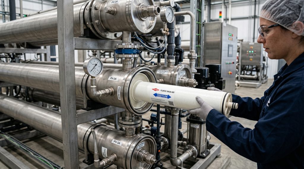
Spiral wound is the dominant configuration for water treatment RO. The membrane is manufactured as flat sheets, layered with feed spacers and permeate carriers, then rolled around a central permeate collection tube. Standard element sizes are 4-inch diameter by 40 inches long (residential/light commercial) and 8-inch diameter by 40 inches long (commercial/industrial).
The spiral wound design offers the best balance of packing density (membrane area per unit volume), fouling resistance, and cleanability. Standard 8040 elements provide 350-440 square feet of membrane area per element depending on the spacer thickness.
Hollow Fiber Modules
Hollow fiber membranes consist of thousands of tiny tubular fibers (0.5-1.5mm diameter) bundled inside a pressure vessel. Feedwater flows either through the fiber bore (inside-out) or around the outside of the fibers (outside-in).
Hollow fiber modules offer extremely high packing density—up to 10,000 ft² per module—but are more susceptible to fouling and harder to clean than spiral wound elements. They’re more commonly used in ultrafiltration/microfiltration pre-treatment than in the RO stage itself, though some manufacturers offer hollow fiber RO modules for specific applications like high-purity water production.
For the vast majority of desalination and industrial water treatment applications, spiral wound TFC polyamide elements remain the standard. That’s what you’ll find in AMPAC’s RO membrane catalog, which stocks elements from major manufacturers sized for residential through industrial applications.
Key Performance Parameters: What the Spec Sheet Really Tells You
Salt Rejection
Expressed as a percentage, salt rejection indicates how much dissolved salt the membrane removes from the feedwater. A membrane with 99.7% NaCl rejection treating 35,000 ppm seawater will produce permeate with approximately 105 ppm TDS. That fraction of a percent matters enormously at high salinity levels.
Important distinction: manufacturers publish both stabilized rejection (measured after 24 hours of operation under standard test conditions) and minimum rejection (the worst-case guarantee). Always design around minimum rejection values, not the stabilized numbers from the product brochure.
Permeate Flux Rate
Flux is the flow rate of permeate per unit of membrane area, typically expressed as gallons per square foot per day (GFD) or liters per square meter per hour (LMH). Higher flux means more water per element, but pushing flux too high accelerates fouling.
Conservative design flux rates for different feedwater types:
- Seawater (open intake): 8-12 GFD (13-20 LMH)
- Seawater (beach well): 12-16 GFD (20-27 LMH)
- Brackish water (low fouling): 15-20 GFD (25-34 LMH)
- Brackish water (high fouling potential): 10-14 GFD (17-24 LMH)
- Tertiary wastewater effluent: 10-14 GFD (17-24 LMH)
Exceeding these flux rates shortens membrane life and increases cleaning frequency. A common rookie mistake is to design at the maximum flux the membrane can handle to minimize the element count. You save money on membranes but spend it on chemicals, downtime, and early replacement.
Net Driving Pressure and Recovery Rate
Recovery rate—the percentage of feedwater converted to permeate—directly impacts system economics. Higher recovery means less feedwater pumping and less brine disposal. But recovery is limited by the osmotic pressure of the concentrate and the risk of scaling.
Typical recovery ranges:
- Seawater: 35-50% (limited by osmotic pressure, which exceeds 400 psi at high recovery)
- Brackish water: 75-90% (limited by scaling potential—silica, calcium sulfate, barium sulfate)
- Wastewater reuse: 75-85% (limited by organic fouling and scaling)
Seawater vs. Brackish Water Membranes: More Than Just Pressure Ratings
This is where membrane selection gets specific. Seawater and brackish water membranes are engineered differently, and using the wrong type will cost you performance.
Seawater Membranes
Designed for feedwater with 20,000-50,000 ppm TDS. These membranes have a tighter polyamide layer that provides 99.5-99.8% NaCl rejection but requires higher operating pressure (800-1,200 psi). They come in standard (high rejection) and high-flux variants. High-flux seawater membranes trade a small amount of rejection (99.5% vs. 99.75%) for significantly higher permeate flow at the same pressure, which reduces the total number of elements needed.
AMPAC’s seawater desalination systems use premium seawater membranes matched to the specific salinity and temperature conditions of each project.
Brackish Water Membranes
Designed for feedwater with 1,000-10,000 ppm TDS. These membranes have a more open structure that delivers higher flux at lower pressures (150-450 psi) but lower rejection (97-99.5% NaCl). Sub-categories include:
- Low-energy (LE) membranes: Optimized for minimum energy consumption; ideal when feedwater TDS is below 3,000 ppm
- High-rejection (HR) membranes: Tighter structure for applications requiring very low permeate TDS
- Fouling-resistant (FR) membranes: Modified surface chemistry that reduces organic and biological fouling; best for wastewater reuse and high-TOC feedwater
- Low-fouling (LF) membranes: Neutral or negatively charged surface that resists colloidal and organic deposition
For commercial and industrial RO systems, membrane selection often involves running projection software (like Dow WAVE, Hydranautics IMS Design, or Toray DS2) to model different membrane choices against the actual feedwater analysis. This isn’t optional—it’s how you avoid expensive trial-and-error in the field.
Fouling and Cleaning: The Maintenance Reality
Types of Fouling
Membranes foul. It’s not a question of if, but how fast and what type. Understanding fouling mechanisms helps you select membranes and pre-treatment that minimize it:
- Biological fouling (biofouling): Bacterial biofilm growth on the membrane surface. The most common and difficult to prevent. Controlled with biocide dosing in pre-treatment (never directly with chlorine on TFC membranes).
- Colloidal fouling: Deposition of fine particles (silt, clay, iron oxides). Measured by the Silt Density Index (SDI) of the feedwater. SDI below 3 is ideal; above 5 indicates significant pre-treatment improvement is needed.
- Organic fouling: Natural organic matter (NOM) adsorption on the membrane surface. Common in surface water and wastewater applications.
- Scaling: Precipitation of sparingly soluble salts (calcium carbonate, calcium sulfate, silica, barium sulfate) as the concentrate stream exceeds saturation limits.
Clean-In-Place (CIP) Procedures
Regular CIP cleaning restores membrane performance and extends membrane life. Standard CIP protocols involve:
- Alkaline cleaning (pH 11-12, 35-40°C): Removes organic and biological fouling. Typically uses sodium hydroxide with surfactants or chelating agents.
- Acid cleaning (pH 1-2, 25-35°C): Removes mineral scale and metal oxide deposits. Citric acid or hydrochloric acid are most common.
CIP frequency varies by application. Well-designed brackish water systems may go 3-6 months between cleanings; seawater systems with open ocean intakes might need cleaning every 1-3 months. If you’re cleaning more often than monthly, it’s a sign that pre-treatment is inadequate or the system is being pushed beyond its design envelope.
Choosing the Right Membrane: A Decision Framework
Here’s the practical decision sequence:
- Start with feedwater analysis. You need TDS, individual ion concentrations, temperature, pH, SDI, TOC, and any specific contaminants of concern.
- Determine required permeate quality. Drinking water? Process water? Boiler feed? Each has different TDS and specific ion requirements.
- Select membrane category based on feedwater salinity: seawater or brackish.
- Choose sub-type based on priority: standard, low-energy, high-rejection, or fouling-resistant.
- Run projection software with the actual feedwater analysis to verify rejection, flux, pressure, and recovery at design conditions.
- Evaluate total cost of ownership, not just membrane price. A slightly more expensive fouling-resistant membrane might save thousands in annual cleaning costs.
If you need help matching membranes to your specific application, browse AMPAC’s membrane selection or contact AMPAC’s engineering team for guidance. They stock membranes from major manufacturers and can recommend elements based on your feedwater data and system requirements.
Key Takeaways
- TFC polyamide membranes are the standard for most RO applications, offering superior rejection and longer life than cellulose acetate alternatives.
- Spiral wound configurations dominate water treatment RO due to their balance of packing density, fouling resistance, and cleanability.
- Design at conservative flux rates (8-12 GFD for seawater, 15-20 GFD for brackish) to maximize membrane life and minimize cleaning frequency.
- Always select membranes based on actual feedwater analysis and projection software modeling, not assumptions or past experience with different water sources.
- Fouling-resistant and low-energy membrane variants can deliver significant lifecycle cost savings even when their per-element price is higher.
Frequently Asked Questions
=== CONTENT END ===